This activity is in preparation for an Unmanned Aerial Systems (UAS) lab at the end of the semester. Dr. Hupy gave the class two separate folders (baseball field and track field) containing UAS images within the city of Eau Claire, Wisconsin taken by a previous class. These images would be used in Pix4D to create a georeferenced mosaic of imagery.
Description:
- What is the overlap needed for Pix4D to process imagery?
- What if the user is flying over sand/snow, or uniform fields?
- What is Rapid Check?
- Can Pix4D process multiple flights? What does the pilot need to maintain if so?
- Can Pix4D process oblique images? What type of data do you need if so?
Yes, Pix4D can process oblique images. The user would need to know at what angle off nadir the images were collected.
- Are GCPs necessary for Pix4D? When are they highly recommended?
They are not necessary, but they are highly recommended when processing a project with no image geolocation. GCPs give scale, orientation, and absolute position information.
- What is the quality report?
It provides all of the metadata behind the processing, such as the amount of overlap between images, the camera used, the coordinate systems, the image positions, etc.
Methods:
 |
| Figure 2: Selecting the type of output image |
 |
| Figure 1: Adding images to Pix4D |
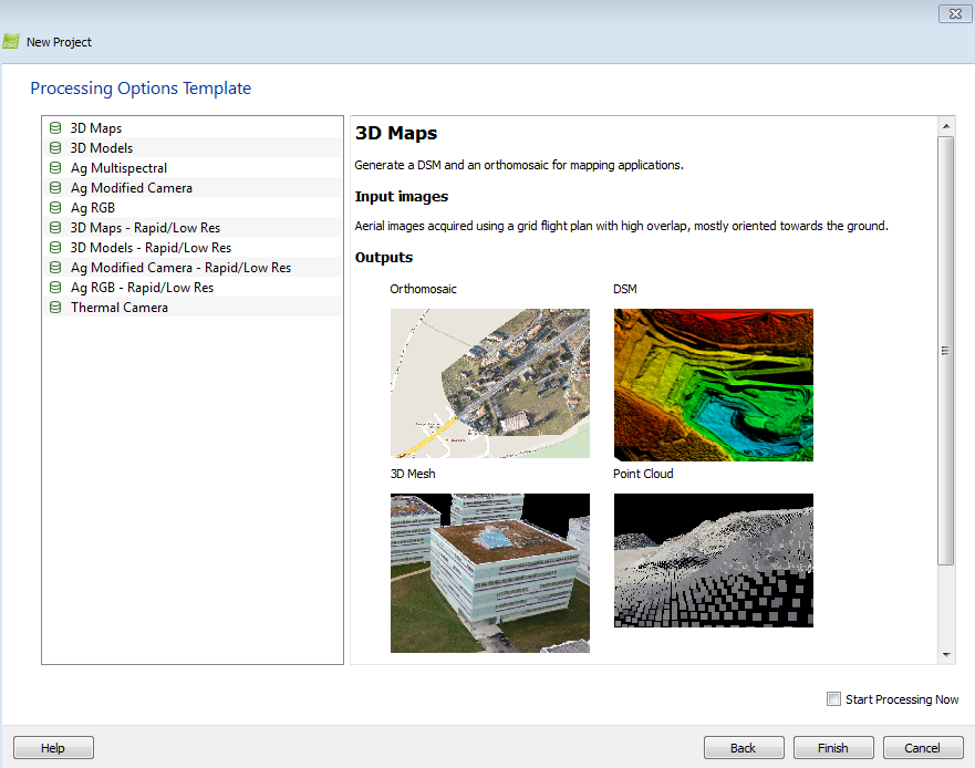
Pix4DMapper Pro was opened to a new project where a setup window appeared. Every image in the file folder of the track field were added (Figure 1). The project was saved to a working folder. From there, a 3D model map view was chosen (Figure 2).
 |
| Figure 3: The initial window of the data in mapview |
After the parameters were set in the setup menu, a view of the locations where the images were tied down to the earth appeared (Figure 3). From here, the processing tab on the bottom left was clicked where a processing window (Figure 4) appeared. This mosaics the images based on points, vertices, and geotags associated with each image. There are three processes that take place to provide a desired output. The first is an initial processing which is a preliminary step to see if the images are able to provide an accurate output mosaiced image. The next is a point cloud which is a 3D look at an object in an image. The final step is the DSM and Orthomosaic. Each of these outputs was saved to the designated working folder and once the initial processing was finished, a quality report was created to help see how well the images overlap as well as a variety of other important information (See Figures Below).
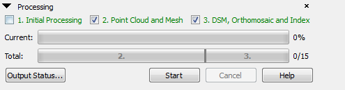 |
| Figure 4: Processing Window |


 |
| Quality report images |
No comments:
Post a Comment